
Growatt inverter turning on and off every morning? Check the startup voltage
My Growatt MIC 2000TL-X kept connecting and disconnecting at sunrise and sunset. The cause was a startup voltage setting the app doesn't show. Here's how to change it over Modbus or from Home Assistant, and what it can't fix.
On this page
If your solar inverter switches on and off repeatedly at sunrise or sunset, connecting to the grid, dropping off a moment later and trying again, this post is for you. People call this hunting. It’s most common when the inverter’s input voltage is low compared with what it was designed for, for example a single panel or a short string.
On many Growatt inverters, the setting behind it is the startup voltage: the PV voltage the inverter waits for before it connects. The app often doesn’t show it, but you can change it over Modbus. If you use Home Assistant with the Growatt Modbus integration, it’s now a control on the MIC profile, from the next release on.
Below is how I found it on my Growatt MIC 2000TL-X, how it became a Home Assistant control, and the part of the problem a setting can’t fix.
Why the inverter keeps switching on and off #
I have a single high-voltage panel, a Maxeon 3: about 65.8 V at its maximum power point and 75.6 V open-circuit. The MIC is built for strings of panels in series. Its nominal input is 360 V, and its working range bottoms out at 50 V.
At dawn, the panel’s voltage rises before it can produce much current. The inverter sees the voltage pass its startup voltage and connects. As soon as it starts drawing power, the voltage sags toward the 50 V floor, and the inverter drops off. The panel recovers, the voltage rises, and the cycle repeats. The same happens in reverse at dusk.
The setting the app doesn’t show #
ShinePhone, Growatt’s app, doesn’t offer this setting for my unit. The inverter does speak Modbus TCP through its ShineWiFi-X stick. Growatt’s Modbus protocol documents list holding register 17 as “Vpv start: input start voltage, 0.1 V”.
Reading it returned 500: a 50.0 V startup voltage, right at the bottom of the inverter’s working range, so it connected at the first sign of light. I wrote 650 (65.0 V) and read it back to confirm:
from pymodbus.client import ModbusTcpClient

c = ModbusTcpClient("<inverter-ip>", port=502)
c.connect()
print(c.read_holding_registers(17, count=1, device_id=1).registers)  # [500]
c.write_register(17, 650, device_id=1)                               # 65.0 V
print(c.read_holding_registers(17, count=1, device_id=1).registers)  # [650]
Only one client can talk to the ShineWiFi stick at a time, so if Home Assistant is polling it, expect a few failed reads on either side while the script runs.
Making it a Home Assistant control #
I monitor the inverter with the Growatt Modbus integration. A one-off script works, but I wanted the setting visible and adjustable, so I added a PV Startup Voltage number entity. I limited it to the integration’s MIC profile, because that’s the only family where I’d confirmed the register works.
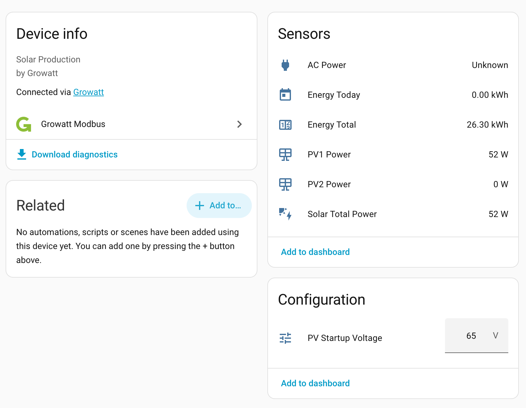
The PV Startup Voltage control under Configuration on the inverter’s device page in Home Assistant.
I sent it upstream as PR #469. The maintainer asked for three changes before merging.
1. Don’t set the range from one panel #
I had capped the control at 72 V, just under my panel’s open-circuit voltage. That works for my setup but not as a limit for everyone. Home Assistant shows a number as unavailable when its current value is outside the allowed range, and the maintainer had readings of 100 V in that register from two other inverters.
No protocol document gives a range for this register, so I used Growatt’s datasheets:
| Model | Factory start voltage | Working (MPPT) range |
|---|---|---|
| MIC 600–2000TL-X | 50 V | 50–500 V |
| MIC 2500–3300TL-X | 80 V | 65–550 V |
| MIN 2500–6000TL-X | 100 V | up to 550 V |
The 100 V readings matched the datasheet. The control’s range became 50–550 V, which covers every model’s working window. The advice to stay below your panel’s open-circuit voltage moved into the docs, as guidance rather than a hard limit.
2. Tests #
The project requires that a new test fails when you remove the code it covers, so you know it isn’t passing by accident. I wrote tests that run the integration’s polling code against a fake inverter, then removed each piece of my change in turn and checked that the matching test failed.
One didn’t. Removing the line that limits the control to the MIC profile broke nothing, because no other profile maps register 17 yet. I added a test where another profile does map it and checked that no control appears there. That one fails without the limit, so it will catch it if register 17 is ever added to another profile.
3. Docs #
The integration’s entity reference said MIC had no controls. It now lists this one, with what it’s for.
What happens if you send a value the inverter doesn’t support? #
A wider range raises a question: what if someone sets 50 V on a model whose own floor is 100 V? I tested it on my inverter, whose window is 50–500 V, by writing 40 V and 600 V directly over Modbus.
The inverter didn’t answer either write. No error code, just silence until the request timed out, and the register kept its old value. Values inside its window were answered normally. So on this firmware, at least, an unsupported value is dropped rather than applied.
The PR is merged, and the control will be in the integration’s next release.
The part a setting can’t fix #
A higher startup voltage stops the inverter connecting on the first weak light. It doesn’t help on an overcast day. On the first cloudy day after the change, the inverter kept switching on and off all morning and produced nothing.
The history showed why. The panel sat at 71–77 V all morning, well above 65 V. With each connection attempt, the voltage dropped to around 55 V and the inverter gave up.
A panel’s open-circuit voltage hardly depends on how much light it gets. Under heavy cloud it still reads around 75 V, but it can only deliver a trickle of current. A voltage threshold can’t tell bright from dim, so on a grey day the inverter keeps trying at almost any setting.
Raising the threshold further would backfire, because open-circuit voltage falls as the panel heats up. On a summer afternoon my panel would sit around 71 V. With the threshold at 72 V, the inverter could refuse to start on the sunniest days of the year.
What I could change is how often it tries. Holding register 18 (“Time start”, in seconds) is how long the inverter waits before each connection attempt. It was 60. I set it to 300, so on a bad day it should try every five minutes instead of every minute. The extra delay costs very little, since the panel produces almost nothing in that light anyway.
The real fix is hardware: a second panel in series would put the string around 130 V, well clear of the inverter’s 50 V floor.
Takeaways #
- If your inverter switches on and off at sunrise, check its startup voltage. Growatt’s Modbus protocol documents are public, and the integration’s repo collects them.
- Set limits from the hardware’s specs, not your own setup. My 72 V cap would have made the control unusable for anyone whose inverter was set higher.
- Check that a test fails without the code it covers. That’s how I found one that couldn’t fail.
- Startup voltage controls when the inverter connects, not how much the panel can deliver. On cloudy days the problem is current, and no voltage setting changes that.
Thanks to @0xAHA for the review and for maintaining the integration.